The Next-Generation
ZT-100 I-Series
Modular from the terminal block to the probe tip — and blow-out safe by geometry, not by procedure
One Platform, Built in Modules
The ZT-100 I-Series has always been an insertion probe — one instrument, entering the line through a single nozzle, measuring water cut where the fluid actually is. The next generation keeps that, and turns everything on either side of it into a choice.
Pick the electronics that suits the installation. Pick the probe tip that suits the line size and the water cut range. The two decisions are independent of each other, because every combination shares the same enclosure and the same mechanical interface — and neither of them changes how the instrument mounts.
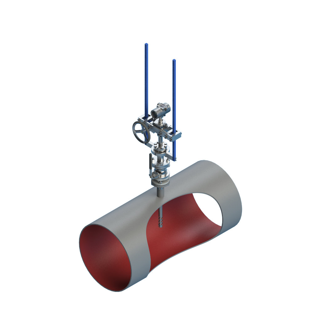
It Cannot Blow Out. Not by Procedure — by Shape.
An insertion probe under process pressure carries one hazard above all others: ejection. The conventional answer is procedure — a packing gland torqued correctly, a locking collar fitted, a retraction sequence followed by a trained operator. The next-generation I-Series answers it with the shape of the probe itself.
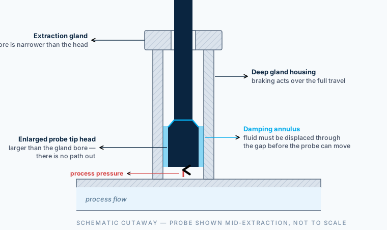
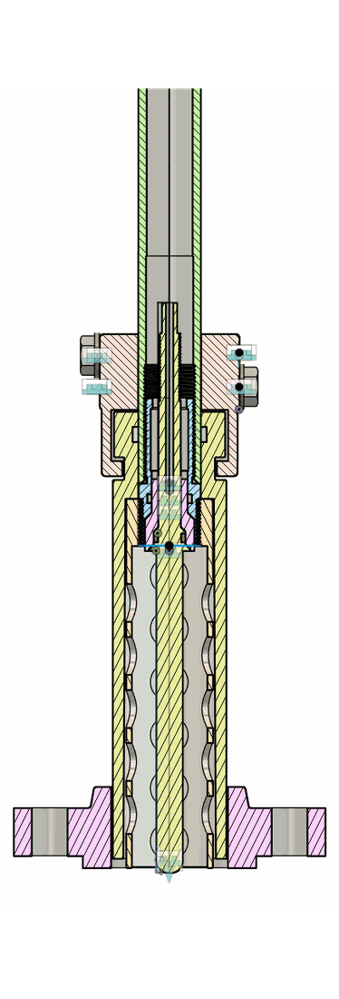
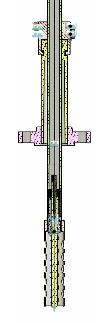
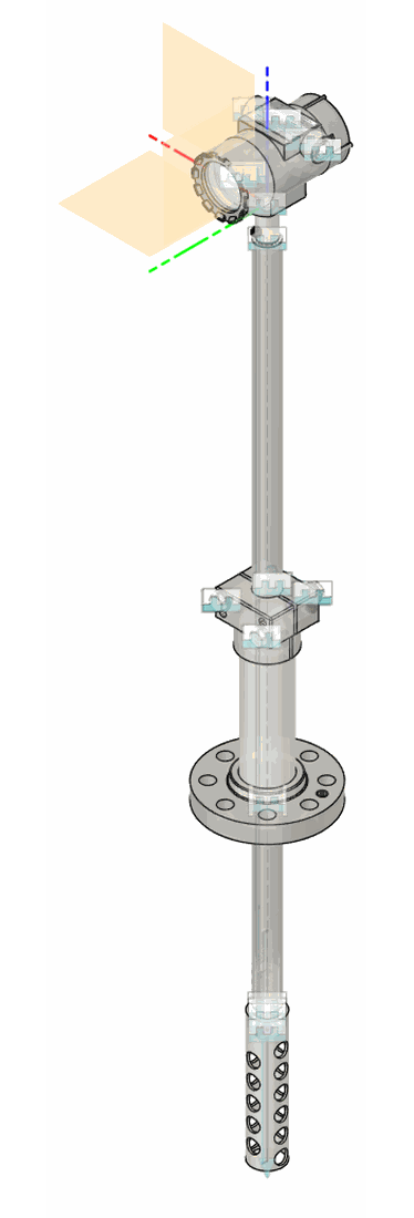
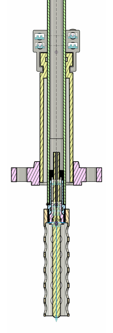
The head cannot pass the gland
The probe tip is formed with an enlarged head that is physically larger than the bore of the extraction gland. Whatever the pressure behind it, there is no opening for the probe to pass through. Retention is a property of the parts, not of the procedure.
Hydraulic braking on the way out
The tip and the gland housing share a common profile. As the head travels up into the housing, the clearance between them closes to a narrow annulus — and process fluid has to be displaced through that gap before the probe can move any further. The effect is a hydraulic brake that bleeds off extraction speed.
Braking across the full travel
The gland housing is deep, so the damping is not a single stop at the end of the stroke. It acts along the whole extraction path, dissipating energy gradually rather than arresting the probe suddenly.
Nothing to set, nothing to forget
The behaviour needs no adjustment, no consumable and no operator decision. It is there the moment the probe is assembled, and it stays there for the life of the instrument.
The retention and damping geometry has been analysed across the I-Series pressure and fluid envelope. Detailed figures are released with the product documentation.
Three Electronics. One Enclosure.
All three options are built into the same enclosure, with the same mounting and the same entries. Choosing between them is an electrical decision rather than a mechanical one — and it can be revisited later without touching the pipework.
The full specification. A 320 × 240 full-colour display puts the reading, the trend and the diagnostics at the instrument, and Bluetooth Low Energy brings configuration and health data to a phone or tablet without opening the enclosure. For installations where instrument power is available.
- 320 × 240 full-colour display
- Bluetooth Low Energy configuration and diagnostics
- 24 VDC powered
- Standard I-Series probe tips
The next generation of the loop-powered board — intrinsically safe, two-wire, and improved throughout. No display: on a loop-powered instrument the available energy belongs to the measurement, not to a backlight. For intrinsically safe loops and for retrofits into existing two-wire infrastructure.
- Intrinsically safe, loop powered
- No display — energy goes to the measurement
- Suits existing two-wire loops
- Standard I-Series probe tips
Full-Cut carries the measurement through phase inversion. Instead of a single fixed excitation frequency it sweeps across a frequency range and reads the difference in the response — which is what makes the water-continuous side of inversion measurable at all. Paired with a probe head of its own.
- 0–100% water cut, through phase inversion
- Multi-frequency, frequency-sweeping measurement
- 320 × 240 full-colour display
- Dedicated Full-Cut probe head
Modular at the Wet End Too
The probe tip is a module in its own right. For the -C and -B2 electronics there are four tip versions, selected on line size and on the water cut range the application needs. Full-Cut uses a head of its own, built for multi-frequency measurement.
Every tip shares the same outer geometry — the same retention profile, the same damping behaviour, the same gland and the same retraction hardware. Changing the measuring range of an installed instrument is a tip change, not a re-engineering exercise.
Configuration Overview
| Electronics | Display | Power | Probe tip | Water cut range |
| ZT-100-C | 320 × 240 colour | 24 VDC | Four versions, by line size and range | 0–25% or 0–65% max |
| ZT-100-B2 | None (loop powered) | Loop powered, intrinsically safe | Four versions, by line size and range | 0–25% or 0–65% max |
| ZT-100-FC | 320 × 240 colour | 24 VDC | Dedicated Full-Cut head | 0–100% |
What Modularity Buys You
One spares list
A common enclosure and a common probe body mean a site running several I-Series instruments stocks one set of mechanical spares — whatever mix of electronics and ranges happens to be installed.
Range changes without re-piping
When a well matures and the water cut climbs past the range the instrument was specified for, the answer is a different tip in the same gland. Not a different instrument in a different nozzle.
An upgrade path that already fits
Because the enclosure and the mechanical interface do not change between the three options, moving from loop-powered to fully powered — or up to Full-Cut — does not disturb the installation.
Safety that does not depend on training
The retention geometry is common to every tip. Whichever version is fitted, and whoever fits it, the probe cannot leave the pipe.
This page is an early look at a product in release preparation. Configurations, specifications and certification status are indicative and subject to change. Contact us for the current release schedule and for confirmation against a specific application.
Talk to Us About the Next-Generation I-Series
Tell us the line size, the pressure class and the water cut range you need to cover, and we will tell you which configuration fits — and when it is available.